Home Networking Setup
Dual-ISP failover, a 24-port PoE switch, eleven cameras, eight access points, and a Mac Studio in the rack. Designed, wired, and crimped personally, end to end.
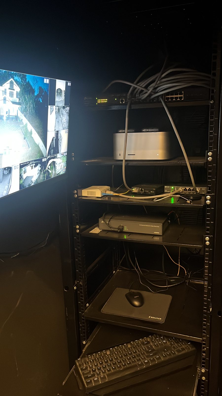
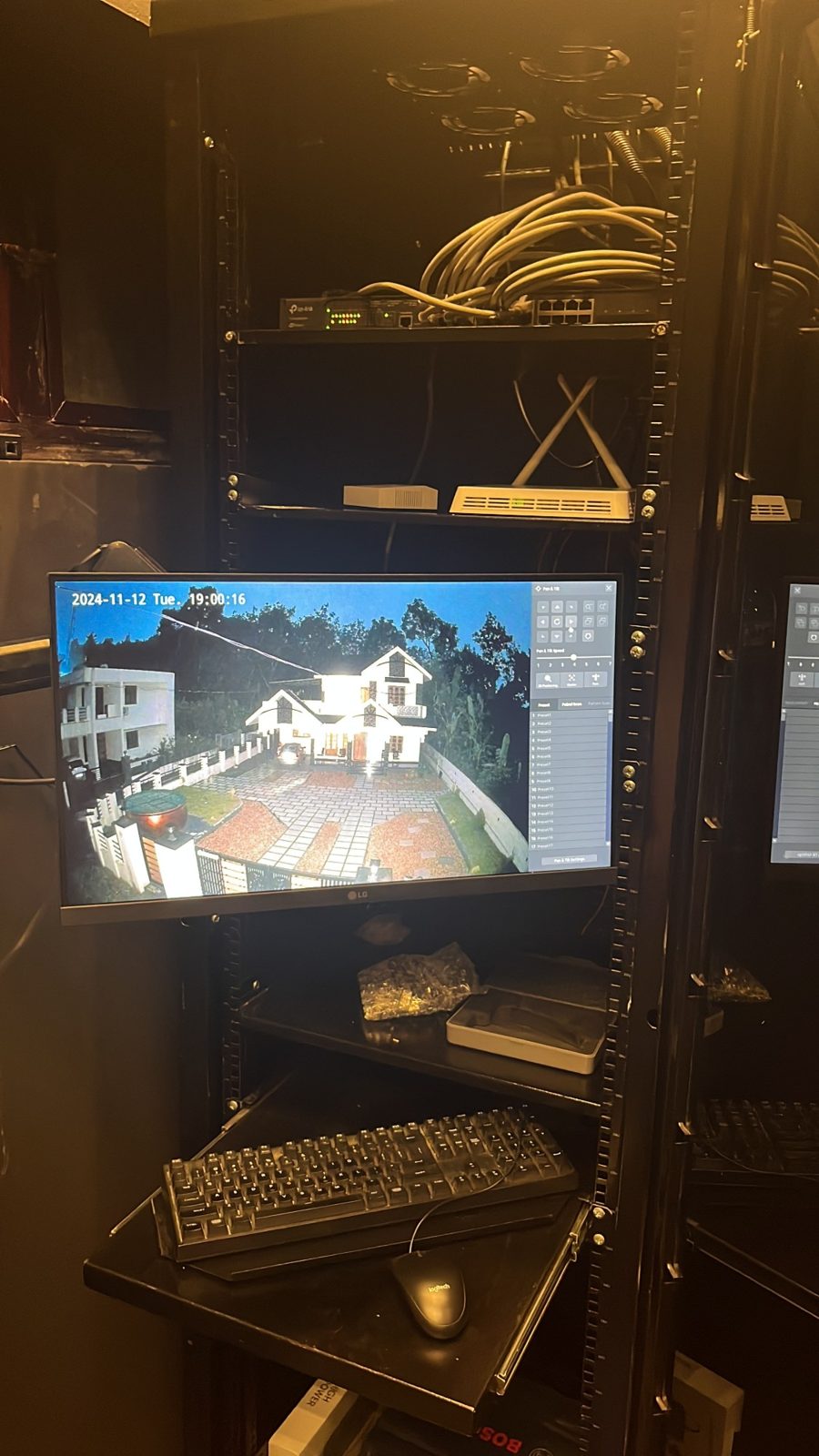
I run production Kubernetes clusters for a living, but my home internet used to be one consumer router doing its best. This project fixed that, and it turned into the most fun crash course in core networking I have had: PoE budgets, routing camera traffic, wireless coverage planning, and managing all of it remotely through a hardware controller. It started with a spool of Cat 6 and a crimping tool, and every termination in the house is mine.
The architecture
Hover over or tap any device to see what it is and what it does. Click to pin it.
Two fiber ISPs come into the house, each converted to Ethernet by its ISP-side router. Both feeds land on a TP-Link ER605 VPN router doing dual-WAN load balancing: if one ISP goes down, traffic fails over to the other automatically, and most of the time nobody in the house notices anything happened.
The router feeds the heart of the setup, a JetStream 24-port PoE+ managed switch. Every access point and every camera hangs off it over a single cable each, power and data together. The Omada OC200 hardware controller manages the whole estate remotely, with its configuration backed up daily to a pendrive, and the Vigi NVR records every camera feed to a 4TB WD drive. The doorbell is the one non-TP-Link camera in the mix, and it still records to the same NVR because both sides speak ONVIF, the vendor-neutral protocol for IP cameras. Mixed-vendor surveillance with zero glue code, which is more than can be said for most enterprise tooling.
And because there was one shelf left in the rack: a Mac Studio, which I use for experimenting with self-hosted LLMs. It is a very short commute from "camera network" to "inference lab".
The bill of materials
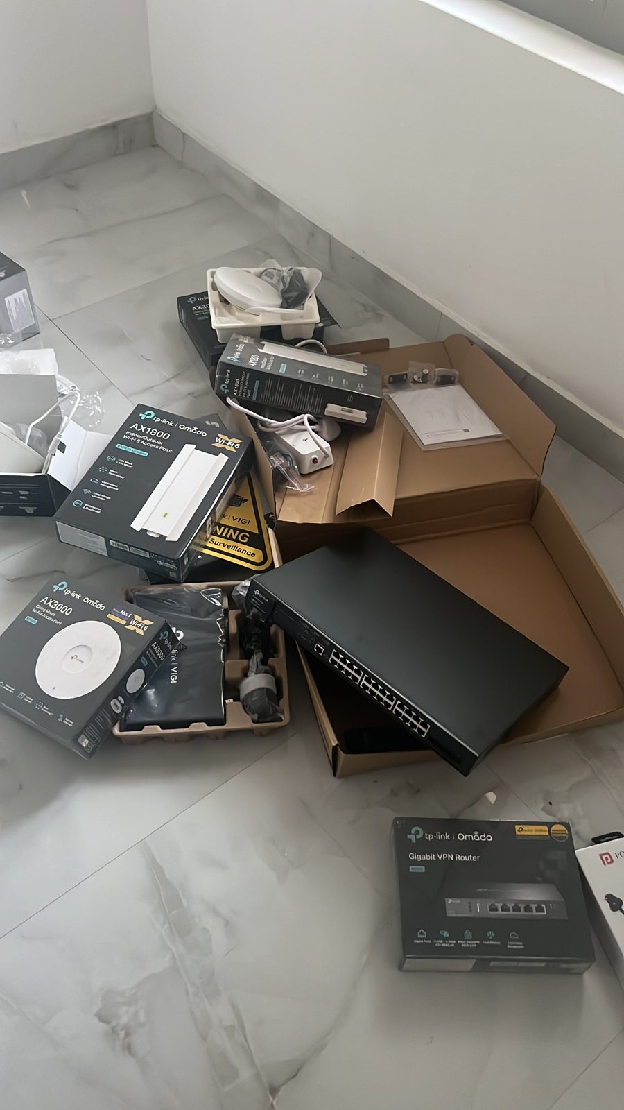
- TP-Link TL-ER605 ↗Omada gigabit VPN router, dual-WAN load balancing×1
- TP-Link JetStream TL-SG3428XMP ↗24-port gigabit PoE+ L2+ managed switch, 4x 10GE SFP+×1
- TP-Link OC200 ↗Omada hardware controller×1
- TP-Link EAP650 ↗AX3000 ceiling-mount Wi-Fi 6 access point×2
- TP-Link EAP610-Outdoor ↗AX1800 outdoor Wi-Fi 6 access point×2
- TP-Link EAP230-Wall ↗wall-plate access point×4
- Vigi NVR1008H ↗8-channel network video recorder×1
- WD 4TB HDD ↗surveillance-class drives in the NVR×2
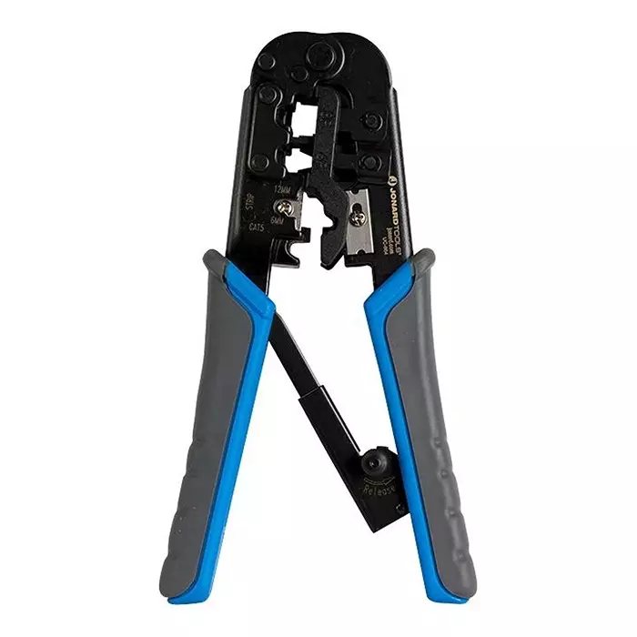
- RJ45 crimping toolstrips, cuts, and crimps in one tool×1
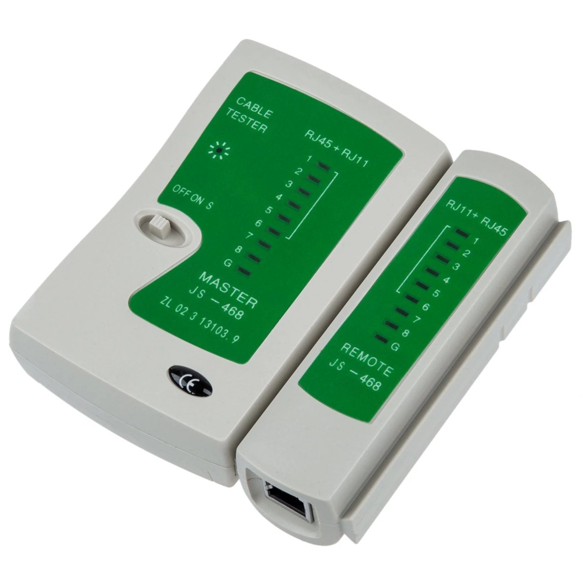
- LAN cable testermaster + detachable remote, RJ45 and RJ11×1
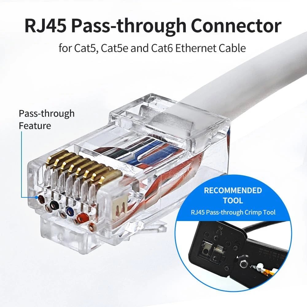
- Cat 6 spool + RJ45 pass-through connectorsevery run cut to length and terminated by hand×1
The build
Nothing here was installed by a vendor. Pulling the cable runs, terminating and testing every jack, mounting the outdoor APs and cameras, and adopting everything into the controller was the project. The parts of networking I had always consumed as a platform engineer, someone else's switch port, someone else's VLAN, suddenly became mine to get right, and debugging a dead run back to a bad crimp teaches you more respect for layer 1 than any outage postmortem.
How to crimp a LAN cable
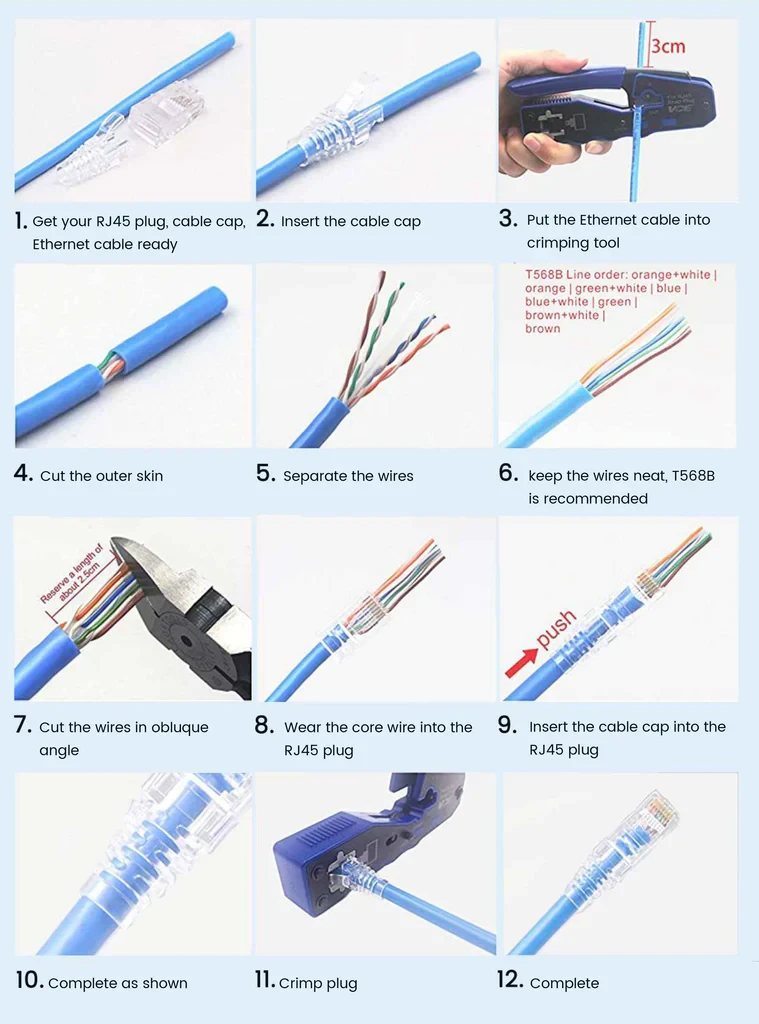
In-wall runs cannot use pre-made patch cables, so every cable in this house was cut to length from a spool and terminated by hand. The process, once you have done it forty times, in twelve steps:
- Get the RJ45 plug, the cable cap (strain-relief boot), and the cable ready.
- Slide the boot onto the cable first. Everyone forgets this exactly once per cable.
- Put the cable into the stripper on the crimping tool, about 3cm in.
- Cut the outer jacket and slide it off.
- Untwist and separate the four pairs.
- Arrange the wires in T568B order: orange-white, orange, green-white, blue, blue-white, green, brown-white, brown.
- Cut the wires flush at a slight angle so they feed in together.
- Slide the wires into the RJ45 plug, jacket seated inside the plug body.
- Push the boot up to the plug.
- Check the colour order through the clear plastic, every wire fully home.
- Crimp, firmly, once.
- Done. Now test it before you trust it.
The pass-through shortcut
Standard plugs make you cut the wires to exactly the right length blind, then hope all eight seated. Pass-through connectors remove the guesswork: the conductors slide all the way through and out the front of the plug, so you can see and verify the T568B order with everything fully seated, and the crimper's blade trims them flush as it crimps. For a first-timer they are the difference between a weekend of frustration and a working house.
Test before you close the walls
A cheap LAN tester is the best money in the whole project. It comes as a master and a detachable remote, so it works across rooms: clip one unit onto each end of a run and it fires each of the eight pins plus ground in sequence, lighting matching LEDs on both units. All eight light in order, the run is good. An LED that stays dark is an open conductor or a bad crimp; LEDs that light out of order are a miswired pair. Either way you find out while the cable is still easy to redo, not after the wall plates are on and the furniture is back. Every run in this house was tested at both ends before the wiring was called final.